What a Tesla coil actually does
Two tuned circuits, energy passing between them, and a voltage that climbs because the circuits agree on a frequency. It was never a way to distribute power.
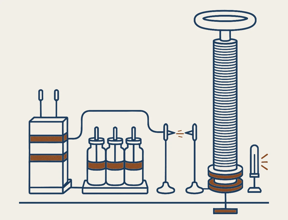
A Tesla coil is an air-cored resonant transformer. Two circuits, each able to ring at a frequency of its own, are tuned so the two frequencies match; a switch dumps energy into the first, and it crosses into the second and arrives as a far higher voltage. The buzz, the streamers, the ozone, the fluorescent tube that lights in a hand held a metre away all follow from that.
It is an instrument, not a power plant. Tesla patented it in 1891 as a lighting apparatus and first showed it as a lecture experiment, and it has spent the hundred and thirty-five years since making invisible fields visible and breaking insulation on purpose. It was never a way of distributing power, and the plainest statement of why not is in the lecture that introduced it.
What is resonance doing here?
Both halves are the same kind of circuit: an inductance and a capacitance wired together, trading energy at a rate fixed by their sizes, f = 1 ÷ 2π√(LC). One half is a large capacitor and a fat coil of a few turns. The other is a tall winding of several hundred turns whose only capacitance is its own surface and a metal doughnut on top. The job is to make the two rates equal, usually somewhere in the tens or hundreds of thousands of cycles a second.
What resonance does is not make energy but repackage it. Take a tank capacitor of 20 nanofarads charged to 15,000 volts. The energy held in a capacitor is ½CV², here 2.25 joules. Move those joules into the second circuit, whose capacitance is not 20 nanofarads but around 20 picofarads, a thousand times smaller. The same ½CV² applies, so the voltage must rise by the square root of a thousand: about thirty-two times, to something near 470,000 volts. Losses take a large bite out of that, but the arithmetic is the machine.
Two consequences follow, and both are routinely lost. The voltage gain has very little to do with the ratio of turns, which is what a mains transformer runs on; it is set by the ratio of the capacitances. And the ledger balances. A gap firing 120 times a second at 2.25 joules a shot draws about 270 watts from the wall. Nothing multiplies energy. The machine multiplies volts by shrinking the container.
One correction, because the wrong version is everywhere. The secondary is often called a quarter wavelength of wire, and the description is Tesla's own: US 593,138 specifies “a length of secondary which is approximately one-quarter of the wave length of the electrical disturbance in the circuit including the secondary coil”. That is not how a coil is tuned. The frequency is set by the winding's inductance and capacitance — which is why bolting a larger toroid on top lowers it without a turn being added.
Why two coils?
A mains transformer winds both coils on one iron core and couples them as tightly as it can. A Tesla coil inverts that twice over. There is no iron, because iron cannot follow a field reversing a hundred thousand times a second; it becomes a heater instead, as the 1891 lecture reported — a thin iron wire held one second inside an energised coil came out at something like 100 °C. And the coupling is deliberately poor, five to twenty per cent.
Loose coupling is what makes the two circuits behave as two rather than one. Energy does not cross in a single stroke. It leaks over cycle by cycle, so the primary empties and the secondary fills across some tens of oscillations; then the exchange reverses and it all comes back. The lower panel of Fig. 2 is that.
Which puts the design problem on the spark gap. It has to stop conducting at the moment the primary is empty. Quench then and the energy is stranded in the secondary, where the audience wants it; quench late and it slides home and burns as heat in the arc. Rotary gaps, air blasts and semiconductor switches all answer that one question.

Why does it make that noise?
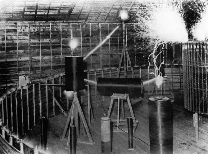
Most of the noise is the gap, not the coil. Each firing is a short arc; the air in it is heated to thousands of degrees in well under a microsecond and expands hard enough to make a pressure step, which is a sound. A simple gap fires about twice per mains cycle, so it hums at 100 or 120 hertz with a stack of harmonics on top. The streamers supply the crack.
Which is why a coil can play music, and why that is less exotic than it looks. The pitch is the firing rate. A solid-state coil gates its primary electronically at any audio frequency, and the streamer becomes a loudspeaker whose diaphragm is the air.
The sound is worth hearing for what it is. A machine that announces itself that loudly is losing a large share of its input inside a switch. It is not the sound of power delivered. It is the sound of the bill.

What was it for in 1891?
Lighting. The document is US 454,622, System of Electric Lighting, filed 25 April 1891 as Serial No. 390,414 and granted on 23 June. It proposes to run lamps on current of a frequency and potential nobody was using, gives “fifteen thousand to twenty thousand per second and a potential of about twenty thousand volts” as what Tesla regarded as the lowest practicable limits, and gets there by charging a condenser and discharging it across an air gap into the primary of an induction coil — the row of apparatus in Fig. 1 and the circuit in Fig. 2.
The public demonstration came before the grant, not after it. Twenty-five days after the filing, on 20 May 1891, the apparatus was shown at Columbia College in New York before the American Institute of Electrical Engineers. The lecture states its object plainly: the machines gave “more than two million reversals of current per minute” — about 16,700 complete cycles a second — and the results bore on “one of the most important problems, namely, the production of a practical and efficient source of light”.
The same lecture settles what the coil was not for. Working through whether lamps could be lit at a distance with no wire between, it reaches this:
It is true that when acting at a distance we have the resonance to help us out … it may be possible to increase the effect qualitatively, and only qualitatively, for we would not get more energy through the device … we cannot get enough energy to render the light practically available … Hence the necessity of directing, by means of a conducting circuit, the energy to the place of transformation.
Lecture to the American Institute of Electrical Engineers, Columbia College, New York, 20 May 1891; printed in T. C. Martin, The Inventions, Researches and Writings of Nikola Tesla (New York, 1894), p. 190.
That is the inventor, in the coil's founding lecture, saying resonance buys volts and not watts, and the energy still has to reach the lamp along a wire. The one time he proposed this winding for distribution, in US 593,138, the scheme was an ordinary transmission line: a step-up coil, a line wire on long insulators, a step-down coil feeding lamps and motors. It was never built.
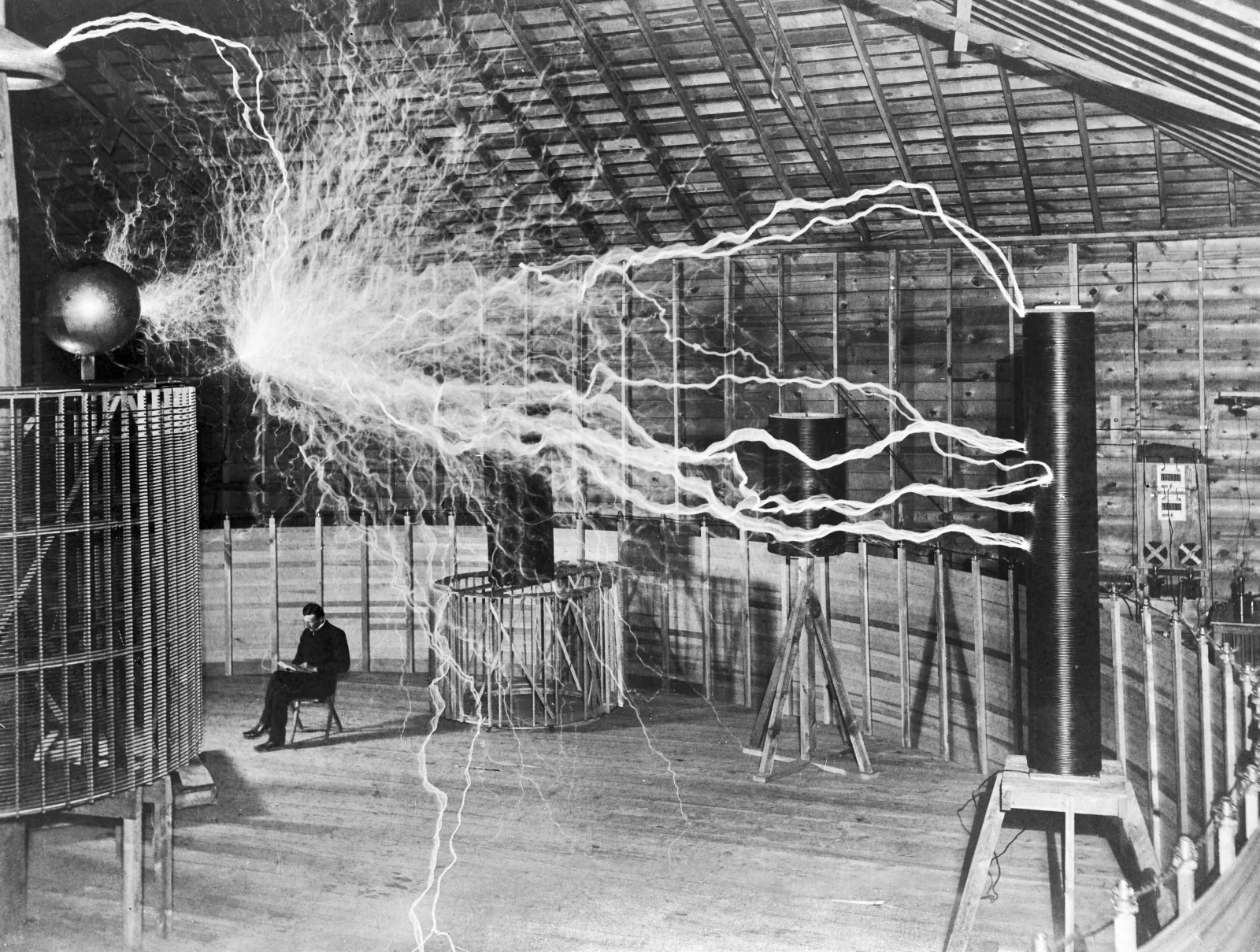
So the free-energy reading is manufactured by the spectacle, not the record. A tube glowing in a hand near a running coil is real, and it is microwatts, coupled out of a machine plugged into the mains. What Tesla later proposed for moving energy without wires was a different apparatus and a different argument, examined in what he actually proposed; the tower at Shoreham had a coal-fired plant beside it.
And what is it for now?
Demonstration first. Griffith Observatory in Los Angeles has run a coil since 1937 — it belonged before that to a Tufts physician who used high-frequency currents on patients — and demonstrates it about nine times a weekday, six minutes at a go. Making an invisible field visible to a room of people is what the apparatus has always been best at.
Second, leak-finding. A handheld high-frequency coil — the Electro-Technic BD-10A is the type specimen, 20,000 to 50,000 volts at about 500 kilohertz, output current held near a tenth of a milliamp — is standard equipment on a glass vacuum line and in neon work. Run the probe along the outside of the glass: at low pressure the gas inside glows, the colour reports roughly how good the vacuum is, and at a pinhole the discharge gathers and points at the fault. Coating inspectors call such a pinhole a holiday, and the same probe finds them in the lining of a metal tank.
Third, proving insulation. Withstand testing of extruded power cable and gas-insulated switchgear is done with resonant sets: a variable reactor is tuned against the capacitance of the test object itself, so the supply need only make up the losses rather than drive the full reactive current of a kilometre of cable. One manufacturer puts the saving arithmetically: at a quality factor of 100, the input power is about a hundredth of the reactive power the object demands. That is also why the standards for testing a cable once it is in the ground, IEC 60840 and IEC 62067, accept any frequency from twenty to three hundred hertz rather than insisting on mains frequency. The set is tuned to the cable, not the cable to the set.
And in pulsed power it survives under its own name. The SINUS electron accelerators, built at the Institute of High-Current Electronics of the Russian Academy of Sciences, charge their coaxial forming lines from a Tesla transformer built into the machine, which is what keeps a repetitively pulsed accelerator small enough to move.
Every entry on that list is a measurement, a demonstration or a laboratory pulse. None delivers energy to a customer — which is exactly what the patent they descend from never set out to do.
The document
US 454,622 — System of Electric Lighting. Filed 25 April 1891 as Serial No. 390,414, granted 23 June 1891. The condenser, the air gap and the induction coil, described as a way to light lamps.
With it, the lecture of 20 May 1891 to the American Institute of Electrical Engineers at Columbia College, printed in full in the 1894 Martin collection, chapter XXVI, pp. 145–197.
Both are in the public domain. The patent appears in context in the list of United States grants.
Primary documents
- US 454,622, System of Electric Lighting, filed 25 April 1891, granted 23 June 1891 — the disruptive-discharge lighting patent, and the source of the circuit drawn in Figs. 1 and 2 above.
- US 462,418, Method of and Apparatus for Electrical Conversion and Distribution, filed 4 February 1891, granted 3 November 1891 — filed first, granted second, and covering the disruptive discharge itself rather than the coil.
- US 593,138, Electrical Transformer, filed 20 March 1897, granted 2 November 1897 — the flat-spiral winding, the quarter-wavelength rule quoted above, and a wired transmission scheme that was never built.
- “Experiments with Alternate Currents of Very High Frequency and Their Application to Methods of Artificial Illumination”, lecture to the American Institute of Electrical Engineers, Columbia College, New York, 20 May 1891. Printed as chapter XXVI, pp. 145–197, of T. C. Martin, The Inventions, Researches and Writings of Nikola Tesla (New York, 1894). Quotations above at pp. 150, 171 and 190; the disruptive-discharge arrangement is described at p. 191.
Further reading
- R. G. Medhurst, “H.F. Resistance and Self-Capacitance of Single-Layer Solenoids”, Wireless Engineer, February 1947, 35–43, and March 1947, 80–92 — the measured self-capacitance which, with the winding's inductance, fixes the resonant frequency.
- Griffith Observatory, “Tesla Coil”, Wilder Hall of the Eye — the 1937 installation, its provenance and the current demonstration schedule.
- Electro-Technic Products, BD-10A high-frequency generator — the published output figures for the handheld leak detector described above.
- Phenix Technologies, AC resonant test systems, tank type (PDF) — a current manufacturer's description of resonant testing, and the source of the quality-factor arithmetic quoted above: “in a high voltage resonant test circuit where Q = 100, the input power required by the test set is only approx. 1/100 (or 1%) of the reactive power required by the test object.”
- HIGHVOLT, WRV T variable-frequency resonant test systems — a manufacturer stating the IEC-conformant band of twenty to three hundred hertz, and the two standards that set it, IEC 60840 and IEC 62067.
- E. Gockenbach and W. Hauschild, “The selection of the frequency range for high-voltage on-site testing of extruded insulation cable systems”, IEEE Electrical Insulation Magazine 16:6 (November–December 2000), 11–16, doi:10.1109/57.887600 — the reasoning behind that band.
- G. A. Mesyats and others, “Repetitively pulsed high-current accelerators with transformer charging of forming lines”, Laser and Particle Beams 21:2 (2003), 197–209 — the SINUS machines, whose “coaxial forming lines … are charged by a built-in Tesla transformer”.
The record on this article
- False “A Tesla coil draws energy out of the air.” A gap firing 120 times a second at 2.25 joules a shot takes about 270 watts from the wall, and the tube that lights in a hand nearby is running on microwatts coupled out of that. Tesla settled it himself in the coil's founding lecture: resonance “may be possible to increase the effect qualitatively, and only qualitatively, for we would not get more energy through the device”.
- Misread source “The secondary is a quarter wavelength of wire.” The rule is Tesla's own, printed in US 593,138, and it is not how a coil is tuned. The frequency follows from the winding's inductance and its own capacitance — which is why a larger toroid lowers it without a turn being added.
- True “It was patented as a lighting apparatus.” US 454,622, System of Electric Lighting, filed 25 April 1891 and granted 23 June 1891. The one distribution scheme Tesla proposed for this winding, in US 593,138, was an ordinary wired transmission line, and it was never built.
Read next
-
Wireless power, and why “free energy” is not what he was selling
He proposed a way to move energy, never a way to make it — and the way he proposed does not work.
-
What the tower at Shoreham was for
The contract J. P. Morgan signed in March 1901 bought transatlantic wireless telegraphy, and the plant that ran the tower burned coal.